 | Panel Log |
|
|
| ||||||
|
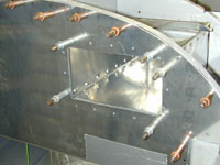
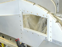
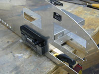
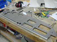
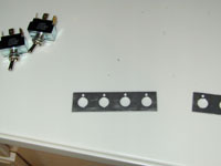
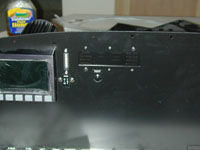
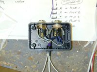
Home Project News February 3, 2021 Project Log Empennage Horizontal Stabilizer Vertical Stabilizer Rudder Elevators Rudder II Wing Kit Wings Fuel Tanks Ailerons Flaps Fuselage Kit Bulkheads Aft Section Foreward Section Top Fuselage Cabin Finish Canopy Cowling Electrical Firewall Forward Fuel System Engine Baffles Misc Miscellaneous Fiberglass Assembly Panel Finishing Up! FAQ Project Notes Project Summary Guestbook Other Stuff | Still cutting square holes in the panel. I also got the spots laid out for the round holes so that I can borrow that instrument hole punch from Marshall. Drilled the holes for the switches. Finally started working on the panel. I started by building the map box and cutting the hole in the panel. Spent some time on the map box. The panel hole wasn't quit big enough and needed to be enlarged. Worked on the structure around the sub panel for the map box and started cutting square holes in the panel for radios.
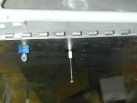
Marshall called and asked if I wanted to fly to Brenham and have lunch. After we flew all over SE Texas looking at airplanes I got a chance to borrow that instrument hole punch and we knocked out the holes for my Dynon, Tru-Trak and my EI fuel gauge. It's hard to believe that is all the round holes that I have but that's it. I drilled the screw holes for the round instruments with my trusty instrument hole jig. I also laid out where I wanted to put the AOA indicator. Oh and went sailing too.
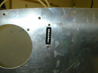
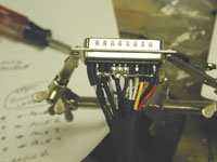
Cut the hole for the AOA indicator. I also punched the hole for the 25-pin D-sub connector that I may use on the control stick wiring. The more I think about this the less I like the idea though.
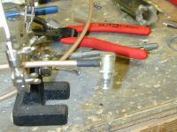
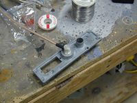
Cut the holes in the panel for the trim indicators Built another throttle / mixture / prop cable mount for the panel. I also drilled holes in each side of the panel for the parking brake cable (pilot side) and cabin heat cable (wife side). Cut the holes in the panel for the Matronics trim controls. Also layed out the holes for the intercom. Finished cutting the last of the holes in the panel and riveted the map box on. I put a coat of primer on it all.
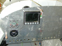
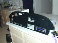
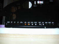
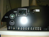
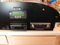
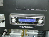
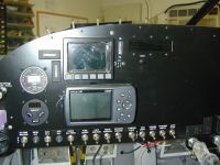
Sanded the panel again and put another coat of primer on it. After that coat set up I wet sanded it and put a coat of black paint on it. I think I'll put one more coat on it and then see how it looks. While paint was drying I mounted the Lightspeed EI module, and started trying to figure out where I am going to run those wires. I also removed the canopy and started taking stuff out of the cabin so that I can get a coat of paint in there. Finished assembling the panel. It's really exciting and now if I only had the cabin painted I could install it and start wiring.
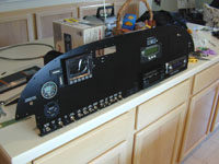
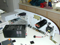
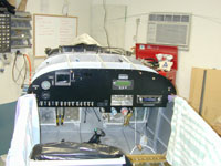
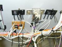
I took the panel into my mad scientist lab and tried to get everything wired that I could on the bench before taking it outside to mount in the plane. I decided that I wasn't going to be able to get all the wire bundles to look like I want without having the panel in the airplane, so I moved all the tools and the panel out of the mad scientist lab and into the airplane factory. I mounted the panel in the plane with clecos.
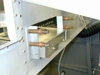
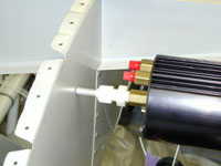
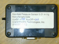
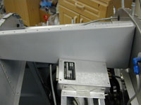
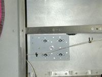
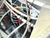
Finished up the control cable support bracket that attaches the control cables to the sub panel. Started running wires. I had to punch a few holes and I think I spent more time scratching my head trying to figure out where the wires are going to go than I did running wires. Spent most of the evening soldering really small wires to the back of the intercom. I have to leave to go offshore later today so I decided to piddle around with the plane some. I mounted the GRT manifold pressure transducer to the sub-panel and finally got around to installing the bulkhead fitting and the hose to the manifold pressure port on the engine. I tubed up the line to both the manifold pressure sensor and the Lightspeed electronic ignition. I cut some more holes in the firewall for the electronic ignition cables as well as some other wires.
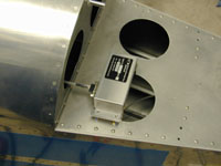
Started working on mounting the magnetic sensor for the Dynon D-10. Finished mounting the Mag sensor and pulled all the wire to wire it up. Also finished all the power wiring to the Dynon. Finished wiring up the Lightspeed Electronic ignition and the strobe power supply stuff as well.
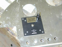
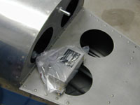
Mounted the brain box for the Proprietary Software Systems AOA indicator. Glued some more of those little stick on wire holders to different places on the panel.
Wired up the master contactor to the switch and turned it on. After checking that all the right voltages were going to all the right busses I checked the pins on the connector for the Dynon and then put a fuse in and turned it on.
Wired up the Aux feed to the essential buss. This is the switch that feeds the e-buss if the master buss is down. I also piddleed around with that cabin heat cable again. Today I built a bracket and hooked up the parking brake cable. I started wiring the AOA indicator. I also hooked up the static an pitot lines to the AOA and the Dynon. While I was in the back of the plane I pulled the rudder cables back through the cabin again.
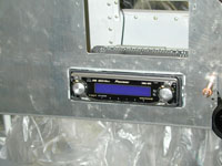
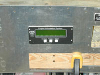
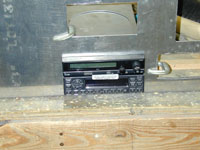
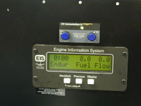
Finished enough of the AOA wiring to power it up and see if it works. I still have to hook up the annunciator, flap switch and audio. I uploaded the latest firmware into the Dynon EFIS-D10. It worked flawlessly. I played around with the checklists a little bit. I still have some configuration to do to get it perfect but I think I'll be really happy with this box. I started wiring up the GRT EIS-4000 Engine monitor. I managed to get all of the EGT / CHT's wired as well as power and the manifold pressure sensor. Mounted the fuel pressure and oil pressure senders. Pulled the wires through the firewall for these senders and hooked up all but the grounds. I also hooked up the P-lead wires and pulled them through the firewall. Hooked the P-lead up to the switch in the cockpit. Wired the tach input to this same switch. I also put the OAT sensor for the EIS into the NACA duct on the passenger side and wired it up. Finished all the wiring on the EIS engine monitor (except the annunciator output) and powered it up. It showed a few temperatures that seemed about right but without any calibrations I really couldn't test much. It does work though. I hooked the power up to the MP3/CD player and I also installed my cargo lights, which are nothing more than those cold cathode tubes that people put inside glass cased computers to fancy them up. I mounted them under the seat-back bulkhead. Built a bracket under the co-pilot seat for the two relays that I will use for the flaps. I thought that I could get the flap wiring finished up tonight but it turned out to be a bigger job than I thought. Finally finished the flap wiring, and actually moved the flaps. It's fun to see stuff move.
Finished wiring the Landing / Taxi lights. I also wired up the postition lights. I rigged up a way to test the Wig Wag flashre on the L/T lights and I don't think that I am going to be happy with it. I will probably redo it. Finished the last of the Lightspeed Electronic Ignition wiring by hooking the coax up to the coils. I then started scratching my head about where to put the headset jacks.
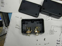
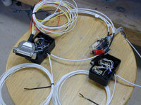
I think I may use a couple of little platic boxes from Radio Shack to put my headset jacks in. This will give the cables some support and eliminate the need to have the little isolation washers. I plan to mount them to the bottom of the sub panel.
I drilled the holes in the sub panel for my little headset jack boxes and I finished soldering the wires to the DRE intercom connector.
Still soldering on the intercom wiring. I managed to get the relay done that I put in for switching com 1 to com 2. (I don't have a com 2 but I think I may expand so I put the relay in just in case.) It is a passive mixing circuit that I got from Garth at DRE. I also started soldering the wires to the headset jacks. When I screwed one up I decided that I had breathed enough lead vapor. Finished soldering the headset jacks in the little boxes and put the intercom wiring harness into the panel. I started hooking up power running the wires around to where they need to be.
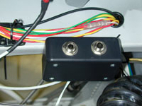
Finished mounting the headset jack boxes under the panel, connected the CD/MP3 player to the intercom and hooked up the PTT wiring to the pilot side stick grip (co-pilot grip is in the mail). I plugged my headset in and gave them to Shannon to put on, then turned on the MP3 player. When her head started bobbing I knew it was working. Once all that was working well I hooked up the audio output of the AOA to the passive mixer circuit and it worked.
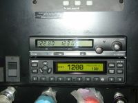
Hooked up the flap switch to the AOA and that completes the AOA wiring. I made a plate for the comm antenna mount and Daryl came by and helped me rivet it to the plane. He also brought another headset so we could test out the intercom some more (I only have one headset). That DRE-244e works as advertised. If it works that well with all the airplane noise I'll be thrilled with it. Once I got the antenna mounted I finished all the rest of the wiring to the ICOM A-200 com radio and turned it on. Nothing :-(. Look at the drawings again, and see the text "jumpers MUST be installed" DOH!! Okay install the jumpers and try again. WHOO HOOO!! I dialed in the CTAF for West Houston and actually heard somebody in the pattern. I pushed the PTT and the TX light came on. It's all very exciting.
Tonight I worked on the Electronics International Dual Fuel Level guage. I got the power and the backlight hooked up but I am still debating on where to punch a hole in the side of the airplane for the probe wires to pass through. They can't go through the other holes because the fuel probes are forward of the spar and I ain't drillin' no holes in the spar to pass wires through. I replaced the Push-on/Push-off switches in my stick grip with momentary switches. I wired up the com flip-flop and memory buttons to the stick grip and started assembling the co-pilot stick grip that I bought from Ray Allen Company. I messed around with the little solid state flasher that I have been toying with for the last few weeks. I make a little circuit board with a microcontroller on it to drive a couple of solid state relays to flash the landing / taxi lights. I'm not real happy with the solid state flasher that I bought from B & C that clicks. Where I come from solid state stuff shouldn't click. So I made my own. It's a little bit of overkill to have a microcontroller on it but it gave me some more programming experience and it keeps the part count low on the board. Finished installing the little solid state lamp flasher that I made. It works pretty well. It's ugly as it can be but it works. I also managed to get power run to my autopilot and turned it on to see if it would work. It did.
I spent most of the day installing the transponder. The Encoder wires were already installed but I put the antenna in and hooked it up and wired power and dimmer control wires to it as well as tightening up the mounting screws. It's good to see it work. I am also trying to share the GPS signal from the GPS-35 that the Tru-Trak autopilot uses so that I can get the automatic ALT / STBY functionality from the GTX-327. We'll see if that works. I had to take the panel trim switches apart and re-wire them so that they would work with my trim set-up and I installed the rear mounting screws for the comm radio. I had left them off because they were a pain and I didn't know whether I would need to take that tray out while messing with the transponder.
Didn't feel like doing much on the project tonight, but I did remember to borrow the little 4-40 tap from work so I went ahead and put the stick grip on the right stick.
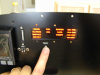
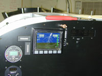
I forgot to hook up the ground on the OAT probe for the Dynon D-10 so I cut that stuff loose and re-wired it. Tonight I messed with all the dimmer circuits and panel lights in the panel. I am going to set my plane up to simply dim the entire panel to a preset level when the position lights are turned on. I'm having to experiment to find the right voltage for each instrument. I managed to get the annunciator re-mounted. It was only temporary last time. I got power to it and started hooking up warning circuits. I think it'll work well. Borrowed the 9-pin D-sub punch from work and put another 9-pin connector on my map box. It'll be for my Garmin GPSMap 296 that I plan to mount on my panel. I want to be able to get the NMEA information out of it while flying. Installed my Garmin GPSMap 296. I bought a marine mount to steal the plastic clip from, and installed it on the panel, right below my Dynon. I intend to mount th antenna that came with it up on the glare shield. I also bought the power / data cable for it so that I could break out the serial port for some data logging.
I decided that I didn't want to have to run the autopilot wires from the wings all the way to the autopilot once the wings were on, so I ran all the wires necessary from the back of the autopilot to floor under the passenger seat, and I'll put a splice there for the autopilot. This will let me get the fuel pump installed and all the covers over the center floor panel without having to worry about how to run those wires all the way up to the panel. Finished wiring up the GPS antennas. |